Your Cart Is Our Priority
Explore our store to see what our products and resources can do for you.

TL;DR:
- A golf cart pedal assembly connects driver inputs to throttle and brake controls, comprising mechanical and electrical components. Proper understanding of system differences between electric and gas models is essential for effective repairs and adjustments. Regular inspection, correct assembly, and precise tuning ensure reliable cart performance and safety.
A golf cart pedal assembly is the complete mechanical and electrical interface that connects driver input to throttle and braking commands, covering the accelerator pedal, brake pedal, linkage cables or sensors, and control switches. Explaining golf cart pedal assembly in full means covering not just the parts but how they interact across electric and gas platforms from EZGO, Club Car, and Yamaha. Whether you are rebuilding a worn unit or diagnosing a non-responsive throttle, understanding the full system is what separates a clean repair from a recurring problem.
The pedal assembly translates physical foot pressure into a signal the cart’s drivetrain can act on. That signal travels differently depending on whether your cart runs on electricity or gasoline.
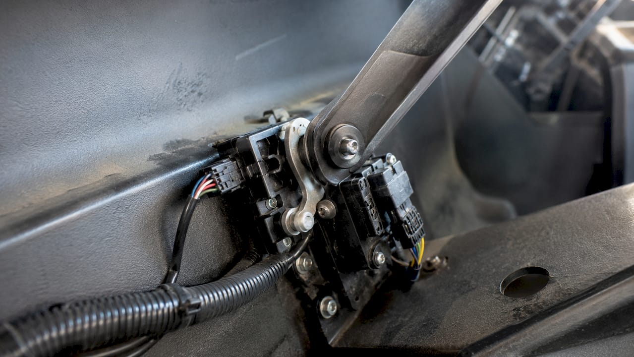
On electric carts, the accelerator pedal depresses a microswitch or activates a position sensor that sends a variable signal to the motor controller. The controller reads that signal and adjusts power output accordingly. On gas carts, the pedal pulls a throttle cable connected to the carburetor, which opens the fuel and air mixture to increase engine speed.
Club Car electric models built before December 6, 2021 use the MCOR (Motor Controller Output Regulator) module. The MCOR translates pedal input into a variable voltage signal the controller reads to manage speed. Faults in the MCOR cause hesitation, surging, or a complete cutoff of drive power. Newer Club Car models use APPS technology, which stands for Accelerator Pedal Position Sensor. APPS uses different electrical logic and requires updated diagnostic and replacement procedures. If you own a post-2021 Club Car, do not assume MCOR repair guides apply to your cart.
EZGO and Yamaha models rely heavily on microswitches located under the driver’s floorboard. The accelerator switch acts as the primary electrical gateway, cutting power to the motor when the pedal is released and opening the circuit when depressed. The 10L0L accelerator switch is a widely used replacement part for EZGO TXT and Yamaha G-series models.
The brake pedal on most golf carts operates a cable or rod linkage that applies friction to the rear drums. Many electric carts also include a safety micro switch on the brake pedal circuit. When the brake is pressed, this switch signals the controller to cut motor output. That interlock prevents the cart from driving while braking, which protects both the drivetrain and the driver.
Pro Tip: Before assuming a controller or motor fault, press the brake pedal firmly and release it fully. A stuck brake micro switch is one of the most common causes of a cart that refuses to move.
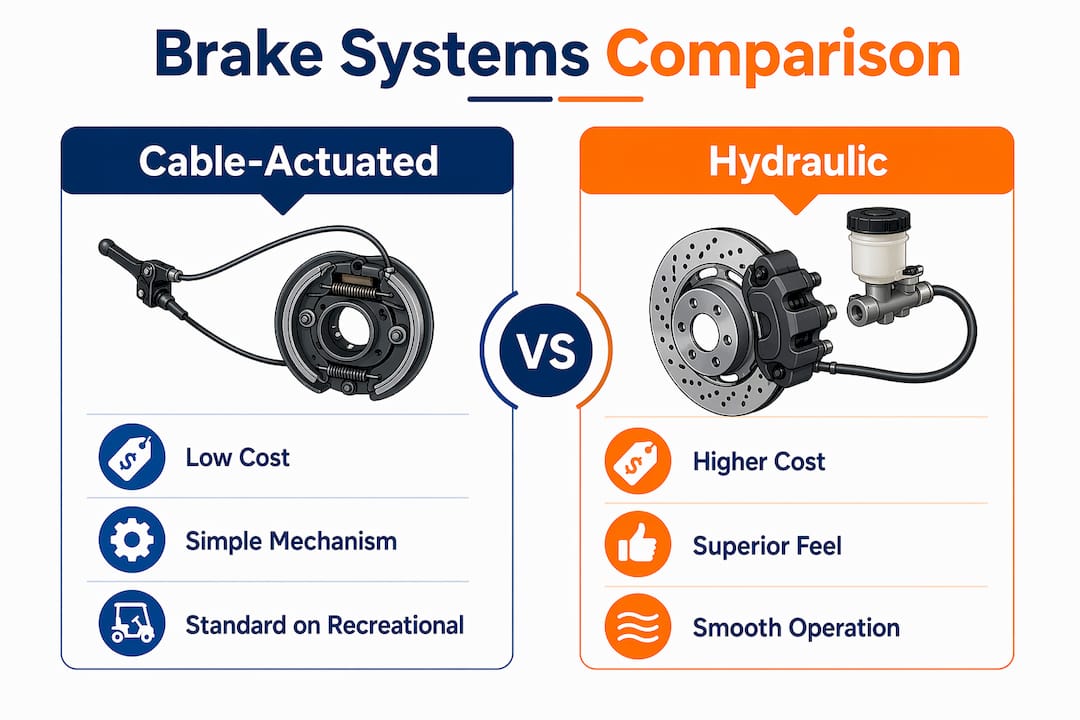
Golf cart pedal systems fall into two broad categories based on how the brake operates: cable-actuated and hydraulic. Each has a distinct profile of cost, performance, and upkeep.
Cable-actuated systems are the standard on most recreational golf carts. They are low-cost, mechanically simple, and easy to adjust with basic hand tools. The trade-off is that cable stretch over time reduces braking feel and requires periodic re-tensioning. Hydraulic brake systems deliver more consistent stopping force and better modulation, but they add complexity through brake fluid, master cylinders, and bleed procedures. Most DIYers working on standard golf carts will deal with cable systems.
Every pedal assembly, regardless of brand, shares a core set of parts:
Compatibility matters more than most DIYers expect. EZGO model years, Club Car DS versus Precedent frames, and Yamaha G-series versus Drive generations all use different pedal box dimensions and mounting patterns. Always verify your cart’s model and year before ordering parts. Golfcartstuff provides an EZGO model year reference that simplifies this lookup.
| Feature | Cable-actuated | Hydraulic |
|---|---|---|
| Cost | Low | Higher |
| Braking feel | Adequate | Superior |
| Maintenance | Simple cable adjustment | Fluid checks and bleeding |
| DIY difficulty | Easy | Moderate to difficult |
| Common on | Most recreational carts | Performance and street-legal builds |
A clean assembly job starts with the right tools and a clear sequence. Rushing the mounting step causes misalignment that no amount of cable adjustment will fix later.
Gather a socket set (3/8-inch drive), combination wrenches, needle-nose pliers, a flathead screwdriver, thread locker (Loctite Blue 243 works well), and a multimeter for electrical testing. Disconnect the battery pack or remove the ignition key before touching any wiring or pedal switches.
Pro Tip: On Club Car DS models, the brake cable equalizer sits behind the rear axle. Adjust brake cable tension at the equalizer nut, not at the pedal end, to get even pressure on both rear drums.
Replace individual parts when the pedal box frame is intact and only one component has failed, such as a microswitch or return spring. Replace the full assembly when the pedal box is cracked, bent, or corroded beyond cleaning, or when multiple components have failed simultaneously. A full replacement is often faster and costs only marginally more than sourcing several individual parts.
Adjustment is where most DIYers lose time. The goal is a throttle that responds immediately without binding and a brake that stops the cart firmly without dragging.
Throttle linkage adjustment requires loosening the locknut near the carburetor or controller input, removing all cable slack, then retightening and testing. The cable should have zero slack at rest but must not pull the throttle open when the pedal is fully released. Test by pressing the pedal to the floor and confirming the carburetor butterfly valve opens completely, or that the MCOR/APPS module reaches its maximum signal output.
On gas models, the governor limits maximum engine RPM. Governor screw adjustments must be made in small increments to avoid pushing the engine into unsafe RPM ranges. Turn the governor screw no more than a quarter turn at a time, then test drive before making further changes. Aggressive governor changes cause premature engine wear and can void any remaining warranty.
Standard brake pedal free play on most golf carts is 1/4 to 1/2 inch of travel before resistance is felt. Less than that means the brakes may drag. More than that delays stopping response. Adjust the brake cable at the equalizer until free play falls within that range.
Common adjustment mistakes to avoid:
Most pedal assembly failures fall into three categories: electrical faults, mechanical wear, and debris interference.
Microswitch failures and loose wiring are the most common cause of a non-responsive throttle. Before replacing any part, inspect every connector for corrosion, broken tabs, and secure seating. A multimeter set to continuity mode will confirm whether a microswitch is opening and closing correctly as the pedal moves. If the switch shows no continuity change, replace it. If continuity is correct but the cart still does not respond, the fault is upstream in the controller or wiring harness. Golfcartstuff’s guide on golf cart wiring troubleshooting covers that diagnostic path in detail.
Worn pivot pins allow pedal arms to shift laterally, which changes the point where the microswitch activates. That lateral play feels like a spongy or inconsistent throttle. Replace pivot pins and bushings as a set when you notice side-to-side movement in the pedal arm. Debris, especially grass clippings and dirt, packs around microswitches and physically blocks the plunger from depressing fully. Clean the switch area with compressed air every few months if the cart operates on grass or unpaved surfaces.
Seek professional service when the APPS module on a newer Club Car shows fault codes that require dealer-level diagnostic software, when brake hydraulic lines need bleeding or replacement, or when the motor controller itself is suspect. Pedal assembly work is well within DIY reach, but controller and hydraulic repairs carry safety implications that warrant professional attention.
A properly assembled and adjusted golf cart pedal assembly is the single most direct factor in throttle response, braking reliability, and overall cart safety.
| Point | Details |
|---|---|
| Know your throttle system | MCOR and APPS systems require different diagnostic and repair procedures depending on Club Car model year. |
| Use thread locker on all fasteners | Vibration loosens pedal assembly bolts over time, causing throttle inconsistency and safety risks. |
| Verify model compatibility first | EZGO, Club Car, and Yamaha use different pedal box dimensions; confirm year and model before ordering parts. |
| Adjust cable tension precisely | Throttle cable must have zero slack at rest without holding the throttle open when the pedal is released. |
| Inspect switches before replacing parts | Corrosion and debris on microswitches mimic controller faults; clean and test before buying new components. |
The most common mistake I see from DIYers is skipping the compatibility check and ordering a pedal assembly based on cart brand alone. Club Car DS and Precedent models use different floor pan geometries. EZGO RXV and TXT pedal boxes are not interchangeable. That one oversight costs time and return shipping fees that a quick model year lookup would have prevented.
The second thing I have learned is that thread locker is not optional. I have seen pedal assemblies on carts used on hilly terrain develop throttle creep within a season simply because the mounting bolts backed out a few turns. Loctite Blue 243 takes 30 seconds to apply and prevents that entirely.
The shift from MCOR to APPS on newer Club Car models is the biggest technical change in pedal system design in the last decade. Many repair guides online still reference MCOR procedures. If your cart was built after late 2021, those guides will send you in the wrong direction. Always confirm which system your cart uses before starting any electrical diagnosis.
My honest advice for any DIYer: buy a quality multimeter, learn to read a wiring diagram for your specific model, and do not skip the test drive after every adjustment. The pedal assembly is simple enough that most repairs are a Saturday morning job. Treat it with the same attention you would give a brake job on a car, and your cart will reward you with years of reliable performance.
— Roshan
Golfcartstuff stocks genuine pedal assembly components for Club Car DS, Yamaha G-series, and EZGO models, including microswitches, throttle cables, pedal boxes, and MCOR replacement units. Every part is listed with model year compatibility so you order the right fit the first time. Whether you are doing a full assembly replacement or tracking down a single faulty switch, the Club Car DS parts catalog is the fastest way to find what you need. Yamaha owners can browse the full Yamaha G1-G22 parts selection for model-specific components. Golfcartstuff makes it straightforward to get your cart back on the course without guessing at compatibility.
A golf cart pedal assembly includes the accelerator pedal arm, brake pedal arm, pedal box bracket, microswitches or position sensors, throttle cable or MCOR/APPS module, return springs, and all mounting fasteners.
Use a multimeter set to continuity mode and test the switch while pressing the pedal. A switch that shows no continuity change when depressed needs replacement, as microswitch failure causes non-responsive or erratic throttle behavior.
MCOR is the throttle input module used on Club Car electric carts built before December 6, 2021. APPS is the newer Accelerator Pedal Position Sensor system used on post-2021 models, with different electrical logic and repair procedures.
Loosen the locknut near the carburetor or controller input, remove all cable slack, then retighten and test. The cable must have no slack at rest but must not pull the throttle open when the pedal is fully released.
Replace the full assembly when the pedal box frame is cracked, bent, or heavily corroded, or when multiple components have failed at the same time. Single-component failures like a worn microswitch or broken return spring are best handled with targeted part replacement.
Explore our store to see what our products and resources can do for you.

Leave a comment