
Your Cart Is Our Priority
Explore our store to see what our products and resources can do for you.

Battery cables are the main current highway in any vehicle’s electrical system. They carry high-amperage DC power between the battery, starter motor, alternator, and every load downstream. When they fail, nothing else works right. Start your diagnosis at the terminals: look for loose clamps, green or white corrosion buildup, and cracked insulation before chasing any other electrical fault.
Here is what to check first:
Battery cables are the highest-current, lowest-resistance path in any vehicle electrical system, and connector assembly quality determines whether they stay that way.
| Point | Details |
|---|---|
| Core function | Battery cables carry high-amperage DC current between the battery, starter, and all downstream loads. |
| Sizing rule | Match AWG to peak current and total cable length and keep voltage drop under 3%. |
| Top failure cause | Mechanical-only crimps and corroded terminals create high-resistance hot spots that generate heat and eventually melt. |
| Maintenance interval | Inspect cables and terminals every 6 months; replace both positive and negative runs together when either shows damage. |
| Golfcartstuff | Stocks Club Car, EZGO, and Yamaha replacement cables and terminal hardware; contact support for model-specific fitment help. |
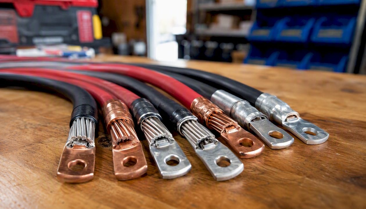
A battery cable is a short, heavy conductor that physically connects the battery’s positive and negative terminals to the rest of the vehicle’s electrical circuit. That sounds simple, but the construction details matter a great deal.
Conductors are almost always stranded copper, not solid wire. Stranded construction handles vibration without cracking, which is critical in engine bays and golf cart frames. Automotive battery cable specifications from IEWC confirm that heavy-gauge stranded copper is the standard for low-voltage DC systems precisely because it survives the heat, oil, and vibration that solid wire cannot.
Insulation is the outer jacket that protects the conductor. Three types dominate:
Terminals and lugs are the metal connectors crimped or soldered onto each cable end. Ring terminals, bolt-on lugs, and clamp-style battery terminals are the most common styles. In a 12V automotive circuit, the positive cable runs from the battery’s positive post to the starter solenoid and fuse block. The negative cable connects the battery’s negative post to the chassis ground and engine block, completing the return path for every circuit in the vehicle. In a 48V golf cart battery bank, the same principle applies across a series string of six or more batteries.
Every cable in a vehicle’s electrical system obeys one equation: V = I × R, where V is voltage drop, I is current in amperes, and R is the cable’s resistance in ohms. The cable’s job is to keep R as low as possible so that voltage drop stays small and the full battery voltage reaches the load.
Consider a starter motor that draws 150 amps during cranking. If the positive cable has a resistance of just 0.01 ohms, the voltage drop across it is 1.5 volts (150A × 0.01Ω). Double the cable length and you roughly double the resistance, which doubles the drop. That is why a long battery-to-starter run in a truck or RV needs a thicker gauge than the same run in a compact car.
Voltage drop in action: a 4-foot positive cable in 2 AWG might drop 0.3V at 150A. The same current through 10 feet of 4 AWG drops closer to 1.2V. That difference can be the margin between a confident crank and a slow, labored start on a cold morning.
The same math applies to inverters and solar charge controllers. A 2,000-watt inverter on a 12V system draws roughly 167 amps continuously. Even a short, undersized cable run will waste watts as heat rather than delivering them to your appliances.
Choosing the right conductor and insulation for your application is not a one-size-fits-all decision.
Conductor options:
Insulation options and their ratings:
Pro Tip: In marine and coastal environments, always choose tinned copper with an SGX or XLPE jacket. Bare copper in salt air corrodes at the strand level, where you cannot see it, until resistance spikes and the cable fails under load.
For golf carts running LiFePO4 lithium battery packs, cable sizing becomes even more critical because lithium batteries can deliver surge currents that exceed what older lead-acid packs produced, and undersized cables will heat up fast.
Good connector quality and insulation rating are primary selection factors alongside conductor choice. A premium conductor paired with a cheap, poorly crimped terminal is still a failure waiting to happen.
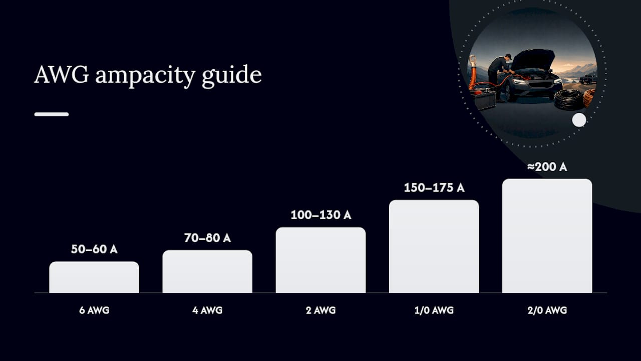
AWG (American Wire Gauge) runs counterintuitively: a lower number means a thicker wire. 2 AWG is much heavier than 8 AWG. Battery Skills’ gauge guide explains that cable gauge selection depends on two variables: the maximum current the cable must carry and the total cable length (positive run plus the negative return path).
General ampacity rules of thumb for 12V/48V DC systems:
On a 12V system, it is 0.36V. Exceed that threshold and starter performance degrades, inverters may fault, and battery chargers may not regulate correctly.
In hot engine compartments, derate further and consider one gauge larger than the table suggests, because heat reduces a conductor’s effective ampacity.
Pro Tip: Always measure round-trip cable length, not just the one-way run. A 5-foot positive cable paired with a 5-foot negative return is a 10-foot circuit for resistance calculation purposes.
Battery cables show up in every system that moves DC power from a storage source to a load.
Automotive starting and charging circuits are the most familiar use. The positive cable carries starter surge current (often 150–300A for a few seconds), then settles into carrying alternator output back to the battery. The negative cable grounds the engine block and chassis.
Golf carts running 36V or 48V battery banks have multiple inter-battery cables connecting cells in series, plus main positive and negative runs to the motor controller and solenoid. These cables are shorter than automotive runs but carry sustained high current during acceleration. Understanding the differences between 36V and 48V golf cart battery setups helps owners size cables correctly for each configuration. For fleet owners, avoiding common golf cart fleet maintenance mistakes often starts with cable inspection.
RV and marine house systems add inverters, solar charge controllers, and DC-DC converters to the mix. These loads draw continuous high current, which means cable sizing is driven by steady-state ampacity rather than short-duration surge tolerance.
Solar battery banks connect panels, charge controllers, and battery storage through cables that must handle both charging current and discharge current to inverters. Undersized cables here waste energy as heat around the clock.
Failing cables rarely announce themselves with a single dramatic event. They degrade gradually, and the symptoms often get misdiagnosed as a bad battery or a failing starter.
Watch for these warning signs:
Worn, corroded, or undersized cables cause slow starting, inconsistent electrical behavior, and overheating. Damage often hides under insulation or at grounding points, which is why a visual check alone is not enough. A flex test (bending the cable gently along its length) can reveal internal cracking that looks fine from the outside.
For a deeper look at electrical symptoms in golf carts specifically, the golf cart wiring troubleshooting guide walks through the most common failure patterns.
Cable maintenance is straightforward when done on a schedule. Neglect it and small problems compound into expensive ones.
Inspection checklist (every 6 months or before each season):
Installation best practices:
Pro Tip: Never over-torque terminal bolts. Cracking the battery post or stripping the bolt threads creates a worse connection than a slightly loose one. Use a torque wrench and follow the battery manufacturer’s spec, typically 5–8 ft-lb for most automotive and golf cart terminals.
Proper grounding is as important as the positive cable run. A corroded or undersized ground strap is responsible for a surprising share of mysterious electrical faults in golf carts.
The cable itself rarely fails first. The connection does.
Research from SV Golden Glow’s battery cable white paper identifies improper connector assembly as a leading cause of high-resistance hot spots and terminal meltdowns. Mechanical-only crimps, loose lugs, and improper torque all create elevated resistance at the junction point. Because resistance generates heat proportional to the square of the current (P = I² × R), even a small resistance increase at a 150A junction produces significant heat.
Practical mitigations are straightforward: use a hydraulic or ratcheting crimper sized for the lug, solder after crimping on main battery connections, and inspect terminals for any heat discoloration at every service interval. A terminal that has turned brown or black has already experienced a thermal event and should be replaced, not cleaned and reused.
Battery cables as the weakest link is a well-documented pattern: corrosion, poor installation, and inadequate thermal management increase resistance over time until the cable or terminal fails under peak load. Routine inspection catches this before it becomes a stranded vehicle or a fire risk.
Replacement is straightforward when you measure before you buy.
Pre-replacement checklist:
Buying checklist:
Replacement tips:
For solenoid connections and other high-current junctions, the solenoid replacement guide covers the safety steps and torque specs that apply to the same terminal connections.
Golf carts are where battery cable problems get overlooked the longest. Owners notice the cart feels sluggish and assume the batteries are dying, but the cables are often the real culprit. Inter-battery cables on a 48V pack carry the full pack current through every connection in the series string. One corroded lug in that chain creates a voltage drop that makes the whole pack look weak on a load test.
The most common cable issue seen on Club Car and Yamaha carts is corrosion at the inter-battery connectors, not the main positive or negative run. Those short cables between batteries sit low in the frame, collect moisture, and rarely get inspected. A set of replacement inter-battery cables and 20 minutes with a torque wrench can restore performance that owners had written off as battery aging.
If your golf cart is showing any of the symptoms above, Golfcartstuff stocks replacement parts and accessories for Club Car, EZGO, and Yamaha carts. Whether you need inter-battery cables, terminal hardware, or a full electrical refresh, the Club Car DS parts collection and the Yamaha golf cart parts collection are the right starting points.

Before ordering, measure your existing cable lengths and confirm the terminal style at each end. Gauge and lug size must match your cart’s original spec or the upgrade you’re building toward. If you’re unsure about fitment for your specific model year, Golfcartstuff’s customer support team can help you match the right part to your cart. Reach out before you order rather than after.
Explore our store to see what our products and resources can do for you.

Leave a comment